Troubleshooting Industrial Pumps
May 8, 2020 | By L. (Tex) Leugner
 Photo Credit: nimis69 / Getty Images
 Photo Credit: nimis69 / Getty Images
Depending on design and application, pumps are fitted with high-speed anti-friction or journal bearings, and lubrication systems used may be oil pump pressurized, self-contained oil in a bearing housing, or dry sump systems using oil mist lubrication. In all cases, pumps are subjected to contaminants, wear metals, direct water or condensation, temperature variations (both ambient and operational), and vibration caused by coupling misalignment, piping strain, foundation or base plate settling, or cavitation due to reduced net positive suction head.
1. What considerations do you believe are necessary when selecting pump lubricant?
Logic: The lubricant recommended will always be dependent on pump shaft speed, shaft diameter, bearing types, and method of lubrication. In addition, some newer pump manufacturers recommend PAO (polyalphaolefin) synthetic oil.
Most pumps require mineral-based rust and oxidation (R&O) inhibited oil in viscosities ranging from ISO 32 for some centrifugal pumps, to as high as extreme pressure (EP) ISO 460 for some piston power pumps. Therefore, it is important to follow the manufacturer’s recommendations regardless of the type of bearing lubrication system in use, and it is advisable to establish an oil analysis program for industrial pumps. The conditions monitored should include wear metals, contamination monitoring using ISO particle counts, viscosity, and acid number.
2. When selecting bearings either initially or for replacement, what considerations are important?
Logic: There is a direct relationship between the load rating and the nominal life of all bearings. Theoretically, doubling the load rating can allow for up to eight times the bearing life. There have been effective redesign modifications to highspeed angular contact bearings used in typical pump applications.
These include hybrid bearings using ceramic balls, bearings with high temperature resistant plastic cages, and matched pairs of back-to-back angular contact ball bearings for high-speed applications, controlling both axial and radial loads. Bearing design, selection, and arrangement will depend on API or ANSI pump system design. Every pump bearing application is a complex system of interacting factors. (These factors are noted in Figure 1).
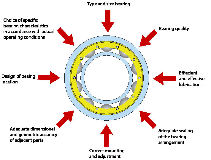
Figure 1 Provided by: L. (Tex) Leugner.
3. What must you consider when initial selection or replacement seals are made?
Logic: The correct specification and selection of seals, and sealing systems, will depend on pump design, application, speeds, and loads. Seal types include radial shaft, labyrinth, gas seal, or mechanical. Mechanical seals can be either single or double depending on the pump type, design, application, and bearing location. Radial shaft seals will incorporate a sealing lip made of a formulation of nitrile rubber.
Certain specifically produced seal lip materials have been developed to accommodate synthetic pump lubricants, or protect against chemically aggressive pump process fluids. Labyrinth seals, sometimes referred to as bearing isolators, feature a non-contacting internal path design that excludes process fluid and particle contaminants while retaining lubrication. They are of metal or plastic material and when installed correctly have a long service life.
Single mechanical seals are made up of a stationary member attached to the pump casing, and a rotating member attached to the shaft. The mating faces of the members perform the sealing. Double mechanical seals are used in applications where the pumped fluid may be toxic or flammable, and leakage to atmosphere cannot be tolerated under any circumstance. Typical applications for double mechanical seals are H2S, hydrofluoric acid alkylation, or sulfuric acid service.
These seals consist of two mechanical seals, a primary and secondary (or backup). The backup or secondary seal uses a flush system with a low flash point fluid.
A relatively new application utilizes two gas seals in a double seal configuration using nitrogen or air as a buffer, maintained at a higher pressure than the pumped fluid, to prevent leakage of the processed fluid to atmosphere. (More information on this is available from API Standard 682).
The operating parameters to be considered when selecting radial sealing systems in pumps are:
• Shaft speed – The majority of standard small-bore radial seals under eight-inch shaft diameter are rated up to 3600 feet per minute, while applications over eight-inch shaft diameter are rated to about 5000 fpm. To exceed these speeds requires special design considerations.
• Temperature – Every seal material has an optimum range, and upgrading the seal material to PTFE or fluoropolymer may be required for excessive thermal limits.
• Pressure – Pressure loading of the seals caused by excessive system conditions, or a fault such as a plugged vent, will mechanically load and distort the sealing contact profile. For example, most standard radial seals are designed for only about seven psi.
• Shaft surface finish – For optimum radial seal performance, consideration must be given to the fineness and type of shaft finish, direction and spiral of the finishing marks and leads, and a surface finish of at least 8-7 μin (micrometres per inch).
4. What operating conditions must the troubleshooter be aware of?
Logic: High pump temperatures, excessive noise, and vibration are conditions that must be investigated. High temperatures may be caused by a binding rotor, misaligned coupling, packing gland misaligned or adjusted too tightly, process fluid too viscous, “pump at run-out” on the performance curve, incorrect bearing lubricant viscosity, or faulty bearings. Excessive noise or vibration can indicate pump cavitation, low suction head, obstruction on the suction side, resonance of certain components, worn or loose bearings, air entrainment, and/or air leaks in the suction line.
5. What potential problems must you be aware of when using vibration analysis as a troubleshooting tool?
Logic: Fan blade and impeller problems, cavitation, flow turbulence, or surging can be detected using vibration analysis. Blade and impeller pass frequencies occur as each blade delivers its contribution to the pumping process. The blades create a frequency as the blade passes the outlet port and large blade pass frequencies with harmonics will be generated in pumps if the vane-to-diffuser gaps are unequal, if the impeller wear ring has seized on the shaft, or if welds fail.
High blade pass frequencies can also be caused by abrupt or sharp bends in piping or ducts, or by obstructions that disturb flow. Pump cavitation indicates voids in the pump inlet generating noise combined with high frequency energy superimposed with harmonics. Impeller vanes will erode as a result and vibrations generated by unbalance can also be generated. Whenever possible, pump inlets must be unrestricted, and even flooded, to reduce unwanted hydraulic and aerodynamic forces.
In conclusion, pumps will operate efficiently and relatively maintenance free if properly selected, carefully installed, and operated and maintained correctly. Oil analysis, vibration analysis, and acoustic ultrasound are invaluable in monitoring the operating condition of pumps. MRO