Everyone wins with good training
Inaugural Machinery Alignment Specialist certified training program took place at the CMVA Technical conference.
July 19, 2023 | By John Lambert
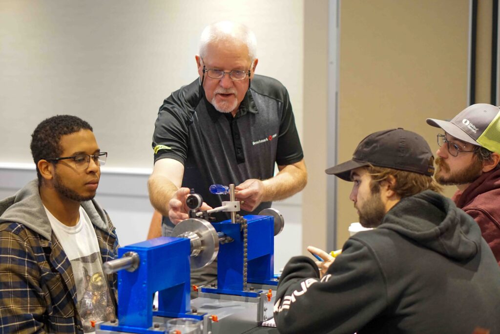 Photo Credit: Colette Keith, CMVA
 Photo Credit: Colette Keith, CMVA
The Machinery Alignment Specialist Level One certified training program was limited to 10 participants, with two instructors at the Canadian Machinery Vibration Association (CMVA) Technical conference. The group included millwrights, engineers, vibration analysts, technicians, and maintenance supervision. Participants came from manufacturing, power generation, natural resources plants and some even owned their own businesses that provide condition monitoring and machine installation.
Machinery Alignment Specialist – Level One
Emphasis at this level was on alignment and pre-alignment principles, what we measure and why. Understanding tolerances and what makes them change, making sure we know the consequences of not following the standard given is the key is to understand the terminology. The core of the training is understanding that machine installation is a process, and shaft alignment is one element of that process.
Four stages of the process are: preparation – to quote a common saying “failing to plan is planning to fail;” inspection – what do we have and can we work with it; measurement/analysis – it’s a process, we measure in a sequence and analyze as we go; correction – if we get the sequence wrong, the correction is wrong.
The critical element is finding and removing machine stress.
Machinery Alignment Specialist – Level Two
This level includes all you see in level one. However, the focus is on shaft alignment of coupled, un-coupled and non-rotating fixed shafts using different methods of measurement tools. Mathematical calculations are used, and graphical modeling to help troubleshoot and overcome issues such as being bolt bound and base bound. This is done using the results from laser/detectors and dial work. Dynamic stress (thermal growth) including calculations and targets is used for training purposes.
The level one that was conducted at the CMVA conference had a hands-on component to it. The participants all did laser/detector alignment and rim and face dial indicator alignment.
Rim and face are still the most recommended method from the coupling manufacturers. Usually, a straightedge is being used to take a rim reading, which is an offset value, and a caliper or feeler gauge taking a face reading, which is an angular value. However, the ANSI standard says quantifiable tools (dial indicators or laser/detector systems) be used to do shaft/coupling alignment. Straightedges, calipers, and feeler gauges are not quantifiable tools, they are subject to human interpretation.
In the Benchmark PDM program, we measure the same thing by using correct tools. Coupling manufacturers do not promote the concept of precision alignment. Using straightedges, calipers, and feeler gauges is a trial-and-error method, and although it is not required for level one, a simple mathematical calculation is added to demonstrate that it does not have to be a hit or miss process. Shaft misalignment is one of the major contributors to machine casing stress, leading to premature machine failure.
Changing the paradigm
All machines are manufactured and machined to exacting geometric dimensioning and tolerancing standards. The foot pads will be machined flat, and if this is a split casing pump, the flat plane of the foot pads will be parallel to the split in the casing. The two pump flanges will also be parallel. There are six bores in a standard split casing pump. That’s two wearing ring bores, two stuffing box or mechanical seal bores and two bearing bores or journals. All these bores are machined so that they are concentric with each other. Flatness, concentricity, perpendicular and parallel are important measurements that are taken when a machine is made.
A machinery alignment specialist knows they must maintain these tolerances for that reason. Machine casing stress is the result of an applied force, which is the result of shaft misalignment, distorted bases, or foot pads, from pipe strain or soft foot.
For example, a large split casing pump, it looks very robust and can support piping; however, they are not designed to support piping. If you pull out the shaft and impeller, it is strong, but it is a hollow casing. A base is recommended to be at least four times the weight of the pump, but here, it is double.
Remember these are not large amounts of movement. A typical ball bearing will have 0.003 thou of clearance for lubrication. If you pull on a casing and change the ovality of the bore by 0.0015 thou. You have halved the lubrication of that bearing, which may be the difference between getting two years of life expectancy or 10. We must look at these machines for what they are, precision-made machines that must be installed so they maintain their geometric dimensions and tolerancing, and for this you need to install using precision.
_________________
John Lambert is the President of Benchmark PDM. He can be reached at john@benchmarkpdm.com.