 Photo 1.
 Contamination of lubricated equipment by dust, dirt, wear particles, process fluids, coolants, carbon soot, acidic products, varnish, sludge, water, and other contaminants will reduce component life dramatically.
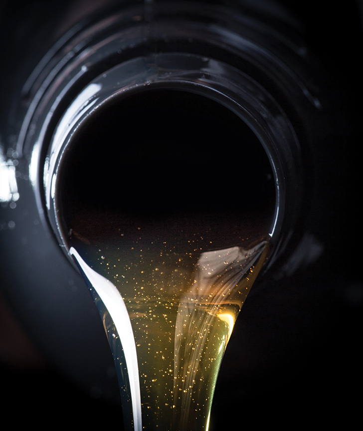
Photo credit: Kesu01 / Getty Images.
By: L. (Tex) Leugner
Statistically, over 70 per cent of lubrication related failures are caused by contamination, which is a machinery killer. In order to eliminate, control, or mitigate the causes of contamination in highly contaminant sensitive systems such as hydrostatic hydraulic pumps (operating at 4500 psi or higher), turbine governor servo control systems, rolling element bearings (where high Hertzian contact pressures can be as little as two micrometres), the lubricant cleanliness must be maintained at 16/14/12 based on ISO standard 4406.
Hard particle contamination causes abrasive wear. When the clearance between two wear surfaces is 15 micrometres, the larger “chips and grit” will not enter and should have been removed by effective filtration. The “ultra-fine particles” are those that do interact with the wear surfaces. These ultra-fines are those that are the result of wear, but not necessarily the cause of it. Ultra-fines are those particles in the two to six micron range that are measured by spectrometric instruments and form the basis of the “wear rate trends” used in component oil analyses programs. The “silt (clearance size) particles” are the “machine killers.”
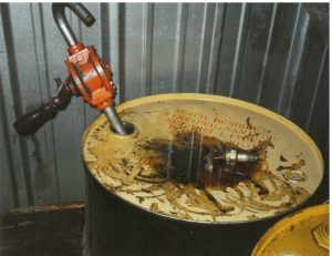
Photo 1. Photo Credit: L. (Tex) Leugner.
1. How does your plant control contamination of new lubricant?
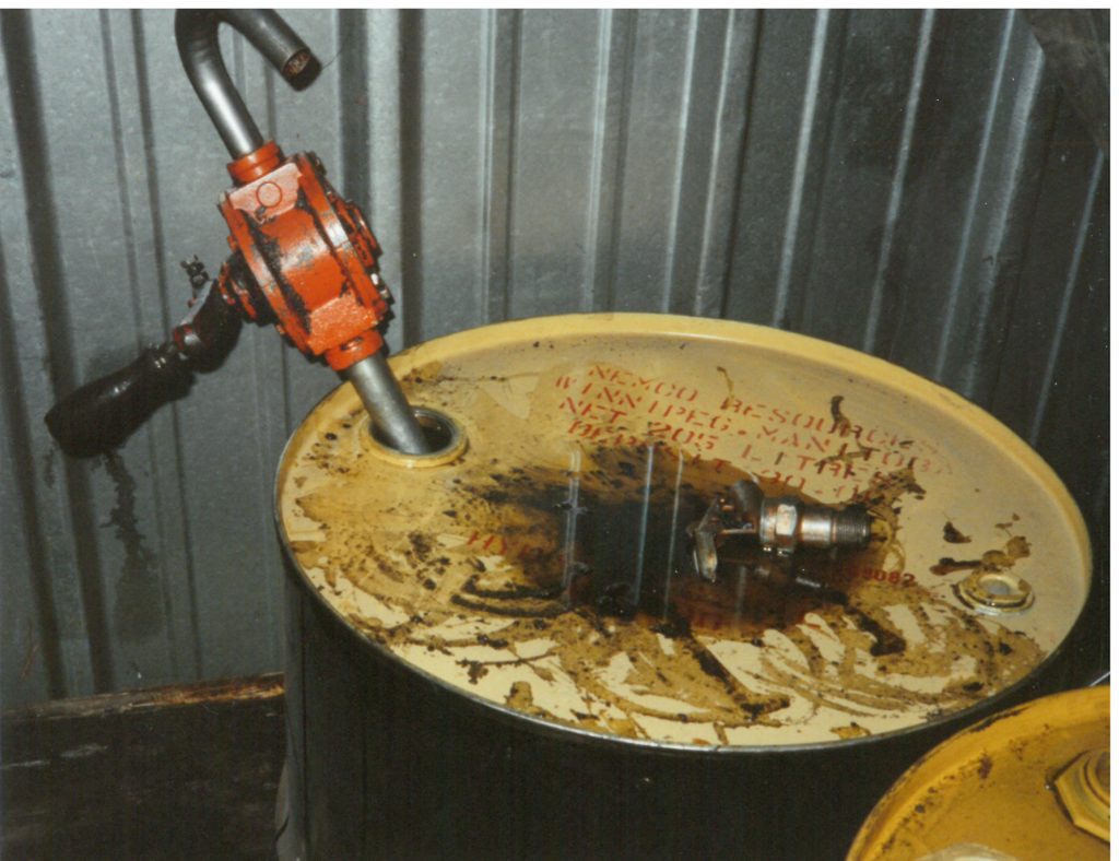
Logic: Contamination control of all lubricants begins with proper storage and handling. Lubricant containers, pumps, and grease guns must be stored in clean, temperature-controlled storage areas and maintained in clean condition, properly labelled for their applicable use with drum bungs properly in place, and new oil should be pre-filtered before use (see Photo 1).
2. Does your plant maintain its equipment in extremely clean condition?
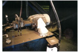
Photo Credit: L. (Tex) Leugner.
Logic: Plant equipment should be kept as clean as possible. Just ¼ of an inch of dirt and dust on critical components can increase operating temperatures by 10 per cent or more, shortening life by up to 50 per cent. The dust covering an oil reservoir will increase the lubricant temperature by several degrees, promoting overheated lubricant and oxidation potential.
Wire mesh filters located in the reservoir filler caps are inadequate for most applications and should be replaced with a reservoir cap containing a four to six micron-rated filter. The illustration may be considered acceptable conditions, but this system or one or more of its components will fail prematurely and equipment reliability will be shortened resulting in costs that could have been avoided. Note the cloth-covered funnel left on the reservoir (see Photo 2).
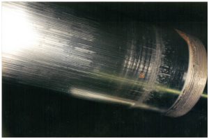
Photo Credit: L. (Tex) Leugner.
3. Does your plant correct all oil leaks immediately?
Logic: There is clear evidence that if oil can escape past hydraulic seals, contamination of dust, dirt, and water will be drawn in when cylinder rods retract. Note the scoring and rust discolouration on the cylinder rod pictured in Photo 3. Oil leaks, no matter how small or seemingly insignificant, are sources of “machine killer” contamination.
4. Does your plant select and use the effective oil filters?
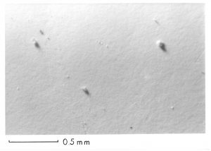
Photo 4: Contamination in new oil taken from a drum with magnification x 500 illustrates that pre-filtering of new lubricants is recommended and encouraged. Photo Credit: L. (Tex) Leugner.
Logic: Filters must meet or exceed the OEM’s standards and should be selected based on the system’s flow rates, operating pressures, filter media type, surface area, pore size, micron rating, and bypass valve opening pressure. If the bypass valve opening pressure is not adequate for the system pressures, sudden or frequent pressure surges will permit unfiltered oil to flow during the time the valve is open, a frequent cause of premature component failure.
The terminology varies, but many systems now call for side stream/bypass/ kidney filtration systems that will ensure filtration at all times. These filters are mounted in parallel to the primary filter and have ratings as small as four, six, or eight microns and contain no bypass valve, thus ensuring that contamination is mitigated or eliminated completely.
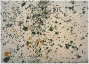
Photo 5: Contamination
found in a hydraulic system with magnification x 500
where particle sizes range from sub-micronic to 100 micrometres. Photo Credit: L. (Tex) Leugner.
Proper filter selection is essential to properly control contamination frequently found in industrial machinery. The three images at right picture case histories that have confirmed excessive levels of contamination using ASTM membrane filtration patch tests and corresponding photography (see Photos 4, 5, and 6).
5. What oil analysis technologies does your plant use to effectively control or mitigate contamination?
Logic: Wear particle analysis by spectroscopy is useless when monitoring contamination particles are larger than approximately six microns. Regularly scheduled contamination monitoring by ISO standard 4406 and subsequent contamination control with the application of effective filtration would have prevented the catastrophic failures illustrated in Photos 5 and 6.
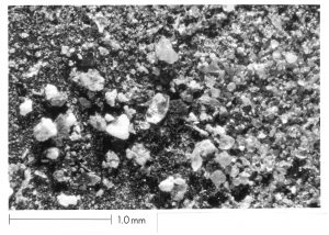
Photo 6: Contamination
found in a pressurized geardrive with magnification x 500 where particle sizes range from sub-micronic to over 200 micrometres. Photo Credit: L. (Tex) Leugner.
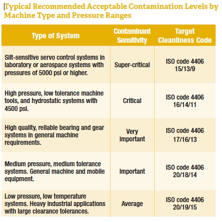
This cleanliness standard measures and monitors contamination in the four, six, and 14 micron particle sizes in industrial recirculating lubrication systems.
These results are then converted to ISO cleanliness standards described in the chart below.
It is virtually impossible to provide a specific ISO cleanliness rating requirement for any piece of industrial equipment. The chart provides guidelines for operators of industrial recirculating lubrication systems. Remember, the smaller the numbers, the cleaner the lubricant. A sound recommendation is to follow the equipment manufacturer’s guidelines; for example, Solar Turbines specifies oil cleanliness be maintained at 16/14/12.
 6. Does your plant use the correct analysis program to monitor water contamination?
Logic: Water is a contaminant that can have a devastating effect on certain equipment types and components. As little as 250 ppm of water in equipment like turbines and hydraulics with turbulent or high oil flow rates may cause foaming, particularly if other contaminants are also present.
In systems with bronze or brass components, corrosion can result, particularly where temperatures are abnormally high. As little as 500 ppm of water in some gear drives can reduce rolling element bearing life dramatically. If water is a continuing contamination problem, a Karl Fischer water analysis should be a regularly scheduled monitoring technique. MRO