The importance of machine base flatness
Now, more than ever, I’m convinced that many machines are installed on bases that are not flat – especially large, newer and more flexible machines that have been set up on old bases.
June 1, 2013 | By By John Lambert
 Photo: Benchmark Maintenance Services. Measuring for flatness on a two-level steel bed.
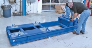
Photo: Benchmark Maintenance Services. Measuring for flatness on a two-level steel bed.
Now, more than ever, I’m convinced that many machines are installed on bases that are not flat – especially large, newer and more flexible machines that have been set up on old bases.
Recently, while doing some training for one of our customers, KSB Pumps Inc., we had an opportunity to do a little experiment with a base and motor. KSB Pumps is a large, well-known pump manufacturer that provides the complete units of base, motor and pump. For many of its customers, the company does the initial installation work. It also handles pump overhaul work, which in many cases includes the re-installation of the pump.
KSB uses an Easy-Laser E710 for shaft alignment and now it has added a D22 Swivel laser transmitter that will allow it to also measure the base for flatness.
Many customers request complete units with the coupling installed and aligned before shipment. This makes sense, because if it is out of alignment, the unit could be damaged during shipping. Many more customers are now also asking that the bases be measured for flatness, as well as being levelled during installation.
Here’s an example of a base we are going to measure for flatness. It is a two-level steel bed. The base specs are: length 104 in., width 38 in., height (upper level) 16 in., height (lower level) 10 in., weight 8,915 lb., motor RPM 3,600. Note: The base is sitting on adjustable chucks. It has been roughly levelled.
With a two-level machine base unit, we start on the upper level by establishing a flat plane. This is done by adjusting the laser beam at three points to zero. This is a machined area, so there is no surprise that when we measure the fourth point, it is also zero. This means we know that the upper level is flat. Zero the laser beam to the first position. Adjust the laser beam to the second and third positions to find the reference.
Next we measure the lower level in relation to the flat upper plane that we have established. For speed, we will only take one measurement per mounting area. However, normally we would take four readings to map out the complete foot pad area.
The procedure is simple and we finish quickly, finding that the base does have a very small amount of twist. We have measured over the actual bolt hole and we easily place the small amount of shim needed on the low points to make the base flat in relation to the upper level.
We are now in a position to install the pump and motor. (Note: The customer could have requested a fully machined base, which would have been flat, but it has chosen a welded plate construction. We know that welded plate is not precise when it comes to flatness.)
Before we do the installation, we conduct a little experiment. We know the base is flat, so if we place three 10-thou shims under three of the feet, we will be creating a twist in the motor because it is not on a flat surface. This actually creates an offset with the bearing – something I call internal misalignment. Once the pump and motor have been installed, we have misalignment because we have used 10-thou shims on three pads only, giving it 5-thou offset at the centre (at the bearing housing).
The motor is now sitting down on the base with the bolts loose and we do have a small gap of less than 2 thou. However, we cannot measure right across the foot pad. So we tighten the hold-down bolts, and then do a traditional measurement for soft-foot, loosening each bolt and checking for a gap under the foot with a feeler gauge. There is no gap detected with a feeler gauge, so we use the laser system to measure, and the laser gives us a result of a 1.5-thou gap across the diagonal plane where the 10-thou shim was missing.
My conclusion is that with all laser systems, the soft-foot measurement result is based on shaft movement/deflection. Although we use and recommend it as a guide, you may not see a true result, because the shaft movement is transferred through the casing, which is flexible, then through the bearing — which has play to the shaft.
The feeler did not work because the sheer weight of the machine pulled it down on to the base. Yes, on smaller, stiffer machines, the foot may spring up. But will the feeler measure all of the twist that is in the base, or just a portion of it? I think the only way to know for sure is to measure the base with the machines removed, using a D22 Swivel laser. MRO
John Lambert is with Benchmark Maintenance Services, Pickering, ON. For more information, visit the website at www.benchmarkpdm.com.
Online Reader Inquiry No. 503