Slippage of Rolling Elements in Ball and Roller Bearings
There is often a discussion about minimum load in bearings to prevent skidding. However, the issue is more complex than a simple relationship with the applied load to the bearing.
September 14, 2021 | By Douglas Martin
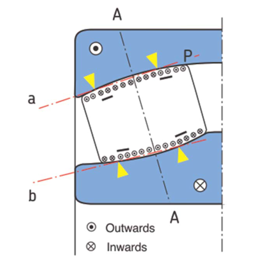 Figure 1 - Here we see the rolling/sliding zones in a ball bearing.
Figure credit: SKF.
Figure 1 - Here we see the rolling/sliding zones in a ball bearing.
Figure credit: SKF. In this article, there will be a breakdown of the different forms of “slippage” and what some of the causes are.

Figure 1 – Here we see the rolling/sliding zones in a ball bearing.
Figure credit: SKF.
The term “slippage”, meaning that at some point on the rolling element/race contact there is relative motion. One surface is going a different velocity (speed and/or direction) than the other surface. One important component of a bearing that will make a significant difference in whether that slippage causes damage or leaves no trace is the lubricant, and specifically the generation of an oil film between the two surfaces. This oil film is the buffer between the two differently moving surfaces.
Normal rolling contact:
With rolling elements, there is always slippage across the contact ellipse. In this picture, the yellow triangles are where there is rolling contact, and all the other areas are sliding contact.
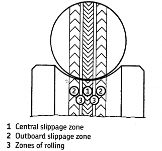
Figure 2
Figure credit: SKF.
So even in a normally operating bearing, there is slippage, and hence, the importance of a lubricating film to separate the rolling surfaces.
Abnormal contact:
Abnormal contact arises from these cases:
Three points of contact:
With a QJ Bearing (4 Point Angular Contact Ball Bearing), the bearing is designed internally to contact in either of two planes, however, there should only be one plane in contact at any given moment. This allows the bearing to accommodate a thrust load in either direction, saving space compared to a pair of single row angular contact ball bearings or a double row ball bearing.
If a radial load is applied to this bearing, it will cause the ball to contact the outer race in two places, while still only in contact with the inner race in one place. The ball will rotate in the plane with the outer and inner ring contact at 180 degrees apart, and the second contact on the outer race will be sliding. For this reason, these bearings are mostly installed with a relieved housing seat such that the outer ring outer diameter is not in contact with the housing bore, preventing an unintended radial load to be applied to the bearing.
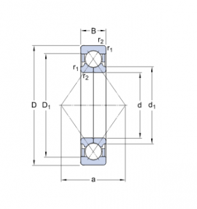
Figure 3
Figure credit: SKF.
Two-point contact on different planes
With a pair of angular contact bearings, there is one bearing that is taking the thrust load and the other bearing is unloaded or sharing a portion of the radial load. With lower speeds, the unloaded bearing will contact the races in two places, and the ball will spin on a single plane with rolling contact with both races.
In higher speed applications, a centripetal force will act on the ball to shift it in a radial direction. When this occurs, the ball will contact the outer race on a different plane than the inner ring contact and one of these contact points, typically with the outer race, will slide.
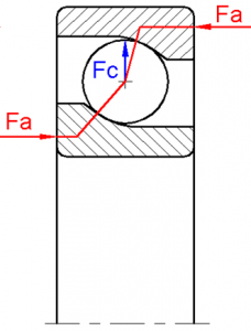
FIgure 4
Figure credit: SKF.
Rolling element speed/moment of inertia
In a radially loaded bearing, the rolling element is moving around the bearing and only in full contact with both races in the load zone. While it is in the load zone, the contact with the inner and outer ring provides traction such that the roller is driven and it rotates.
When the roller is out of the load zone, it is no longer driven by the race contact. It is pushed by the cage through the unloaded zone. While it is being pushed, the frictional contact with the cage bar will slow the rolling element’s rotational speed. Also, any frictional effects of the grease or oil may also contribute to a slowing of the roller rotation. Depending on the size of the bearing, there may be enough of a distance through the load zone such that the relative speed of the rolling element surface and the race surface becomes significantly different.
When the roller then enters the load zone, it quickly accelerates up to the speed of the races. Often with more massive rollers, there will be some distance that the roller needs to get up to speed to equal the race surface speed since the larger roller mass has a greater moment of inertia. It is this brief distance that there is slippage, but often there is adhesive wear.
In fact, this type of slippage occurs in other cases. The basis is the rollers experiencing cyclic loading and unloading. This can also occur with two row bearings with opposite contact angles (such as a spherical roller bearing) in which the axial load is oscillating, causing cyclic loading and unloading of the rolling element set.
One example that I came across was a spherical roller bearing in a newsprint machine. A new felt was installed in the press section, and due to some property of this felt, it introduced a rocking motion in one of the suction rolls. The rocking of the roll could be visually observed. In terms of the bearings inside the roll, there was a spherical roller bearing that experienced a cyclic axial load, in which one race was axially loaded and then the other at a high frequency (i.e. a number of cycles per minute). With each cycle there was a touch down and lift off of the rollers, and since this was a large bearing with massive rollers, with each touchdown there was a skidding event that caused early failures of the bearing.
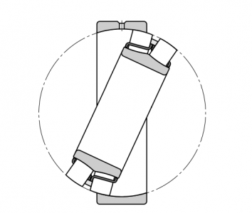
Figure 5
Figure credit: SKF.
Directional differences
In this case, the situation occurs with spherical roller bearings in an application, where the outer ring is rotating, the inner ring is stationary, and there is angular misalignment between the inner and outer ring.
Traditionally, the spherical roller bearing rollers are guided by the rotating inner ring, and due to the nature of the sphered bore of the stationary outer ring, the rollers always have a matching curved surface to run on.
However, when the rotation of the rings is switched, and the outer ring is rotating and the inner ring is stationary, then the track of the rollers on the outer race has a different vector than the rotation of the outer race. There is a slight angular difference that grows as misalignment increases. Although this may be difficult to envision, we can all see a similar case as a transport truck turns a corner and we observe the rear wheels.
Rotating shaft acceleration
A very common application for skidding is in electric motors with cylindrical roller bearings, and most often when these motors are tested in the rewind shop. If there is not a radial load applied to the drive end of the motor during testing, then there is a high risk of roller slippage. Other factors can include the speed at which the motor is started up. In a “full speed” start, the immediate acceleration of the motor can cause slippage, a ramping up of the rpm is best practice to avoid the skidding possibility. MRO
____________
Douglas Martin is a heavy-duty machinery engineer based in Vancouver. He specializes in the design of rotating equipment, failure analysis, and lubrication. Reach him at mro.whats.up.doug@gmail.com.