A selection guide reviewing the merits of system type relative to single- and dual-line parallel systems.
No matter what the type of equipment or its function, system designers are faced with choices at the onset of any project. Take as an example the differences between single-line and dual-line parallel systems. Understanding the benefits of each facet of both the mechanical and control systems will enable a designer to pair the best possible solution with any application.
Single line, parallel automated lubrication
Provided by: SKF.
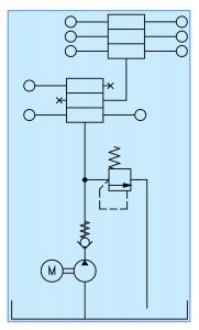
Single line, parallel automated grease systems are commonly implemented for medium to large applications that require multiple lubrication points, often over a fair distance and that require a moderate to large amount of grease per lube point (injector sizes typically range from 0.5cc to 8cc). The layout of this style of system is illustrated in Figure 1.
The primary components of single-line parallel systems are the injector banks, a dump valve and a pump. These injectors typically work on a two- or four-stage charge and discharge cycle. This cycle requires the pump to build pressure/flow in the feedline to the injector bank (filling the metering chamber) and then depressurizing the feedline (facilitated via the dump valve). During this depressurization, the injector’s internal spring will force grease from the measuring chamber out to the servicing lube point. This style of injector is typically adjustable and can also be daisy chained together, making the metering of an exact volume of grease extremely easy to facilitate.
Grease in any system will always take the path of least resistance. As a result, not all injectors will charge or discharge at the same rate. This means that before transitioning from the charge to the discharge cycle, some form of feedback is needed. The most common method for this feedback is the implementation of end-of-line pressure switches. During the charge cycle, the injectors will start to fill and the pressure will remain relatively low. As the injectors reach capacity, this pressure will increase. End-of-line pressure switches are typically set around 1,500-2,500 psi depending on the application.
After confirming all the injectors have charged, the dump valve can then be energized, providing a path to tank and depressurizing the feed line. As the feed line pressure falls below 1,000 psi, the injectors will begin to discharge and once the pressure reaches zero, the circuit is then ready to be charged again. It is good practice to install these pressure switches at the intake of each injector bank because it ensures that new grease flows through the switch during each cycle. Incorrect placement of these switches can lead to decreased equipment life and unreliable operation over time. It is also typical to see the implementation of a pressure transducer located at the output of the pump. This can be tied via logic in the systems controller to ensure proper system operation and providing indication of such things as a failed pump or open feed line.
The cost of the system is heavily dependent on the size of the application, but it is fair to say that most single-line parallel systems hold a moderate-to-high price tag. That cost, however, is not without value – these systems are very reliable and probably the most popular (by install base) for moderate-to-large systems. Capable of feed line lengths that average 100-200 feet, the limitation of these systems is typically dictated by the type of grease used, operating temperature and supply line size.
Dual-line, parallel automated lubrication
Provided by: SKF.
Dual-line, parallel automated grease systems are commonly implemented for large applications that have up to 1,000 servicing lube points. They can also span distances exceeding 1,000 feet, while also delivering large volumes of grease (typical metering valve volumes range from 1.5cc to 5cc). The topology of this style of system is illustrated in Figure 3.
The name “dual line” gives some insight into the heart of this style of system. Whereas the single line system relies on one supply line being charged and discharged, the dual line relies on two separate pressurized feed lines running to each metering valve manifold. This system can be thought of as a hybrid of the single line and progressive systems. Taking strengths from each, its operation is analogous to the combined operation of both systems. The result of this hybrid design is that the dual-line system is the most versatile, robust style of automated greasing system currently on the market.
The operation of this system, like the others, starts with the pump. The pump is energized and builds flow/pressure on feed line A. This is facilitated by the directional control valve mounted at the output of the pump (takes the place of the dump valve for the single-line system), which connects A to the pressure line and B to the tank line. As pressure/flow builds on this line, the metering valves are charged/discharged. Each metering valve contains two spools: the control spool and the metering spool. The control spool is used to control the grease flow paths inside the valve and to alternate from connecting the metering valve to the discharge (lube point) and to the feed line (how it fills). The metering spool both accepts grease that is to be discharged in the next cycle, while simultaneously discharging the grease from the previous charge cycle.
Thus, as line A feeds the metering valve, the control spool is forced to the opposing side – allowing a flow path for the grease to the metering spool on the A side. As the metering spool fills on the A line side, it also discharges the grease that was stored in the previous cycle on the B line side. Once full, pressure begins to build and, like with the single line system, end-of-line pressure switches (or transducers) are used to indicate that all metering valves have cycled. After the A-line cycle is complete the directional control valve at the output of the pump is shifted again and the A line is now connected to the tank, and the B line is connected to the output of the pump – thus initiating the B-line cycle.
The operation of the metering valves is very similar to that of a progressive block, but one with only two stages. The rest of the system’s operation is very similar to the single line system with one important caveat: instead of relying on the spring inside of an injector in combination with the depressurization of the systems feed line, the system instead actively forces the grease out of the metering valve using force transmitted from the current charge cycle. Very elegant in both concept and execution, the active cycling based on flow/pressure form the pump and not a spring is what enables this system to operate over such great distances and what allows one pump to service so many lubrication points.
The sheer mechanical design of this metering valve is not solely responsible for the transmission of grease over such great distances – it only enables it. The force required to transmit this grease still comes from the pump itself, which in dual-line systems typically have much higher operating pressures (on average up to 5,800 psi). This higher operating pressure is what allows the system to overcome the line losses associated with transmitting grease over great distances.
The popularity of the dual-line system is certainly dwarfed by that of the single line and progressive systems based on install base. In truth, these systems are usually only seen on paper, pulp, steel, cement and mining applications, where long continually running systems require both accurate and reliable greasing under extreme operating conditions and typically with very little downtime. Thus, the single biggest constraint of this style of system is its budget and that is why it becomes not a practical option for servicing moderate or smaller applications. With all the same monitoring/system-augmenting options of the single line system, dual-line systems are without question the top of line, most versatile solution for applications that can justify the overall budget.
Control systems
Standalone Control: Standalone controllers are a very popular option and usually come in two forms; integrated controllers provided by manufacturers and custom controllers provided by system integrators. Both options are valid and have their own merits. The manufacturer-supplied controllers are usually fairly easy to install, often have a good price point, and have the advantage of coming pre-programed with a fairly rudimentary operator interface for setting lubrication cycle timing and other system parameters. A major drawback of this style of controller is that it is typically rigid in its application, difficult to troubleshoot and can have long lead times for replacement. For these reasons, some system designers will instead choose to use a plant-standard micro controller that can be programmed by local maintenance or a system integrator. The logic required to program these systems is very basic and can usually be accomplished in 50 lines of ladder logic or less.
Distributed Plant Wide Control: Integrating the control of an automated lubrication system into a plant’s existing distributed control system (DCS) is another popular option. This is probably the best option for moderate to large systems, but not always a practical solution for smaller applications. These systems already exist at most plants, but the integration of them is not without cost; both the cost of hardware and programming can be substantial. For larger systems, however, the cost of integration is usually overshadowed by the benefits of being able to make the equipment’s operation visible for trending over time. For plants where IIoT is an active initiative to aid in improving predictive maintenance, the opportunity to capture this data is invaluable. It enables the owner to both improve the overall effectiveness of the lubrication system, while also capturing information that can be used to predict/monitor the life of the equipment being lubricated. This makes controlling an automated lubrication system by a plant’s distributed control system the ideal solution where costs permit.
Determining the most efficient, economical and practical product for your given application is the key to good system design. Never before has there been a time where so many products of such advanced design have been available for implementation. Continued diligence by system designers to stay current with these technologies is needed to ensure that end users of these great advancements can take full advantage.