Photo Credit: Douglas Martin.
Recently, I was asked to inspect four bearings from two pulleys from an oil sands mine. One of the assemblies was removed due to indications of damage caused by vibration analysis. The four bearings gave a good picture of typical damage and progression of the damage in such an application.
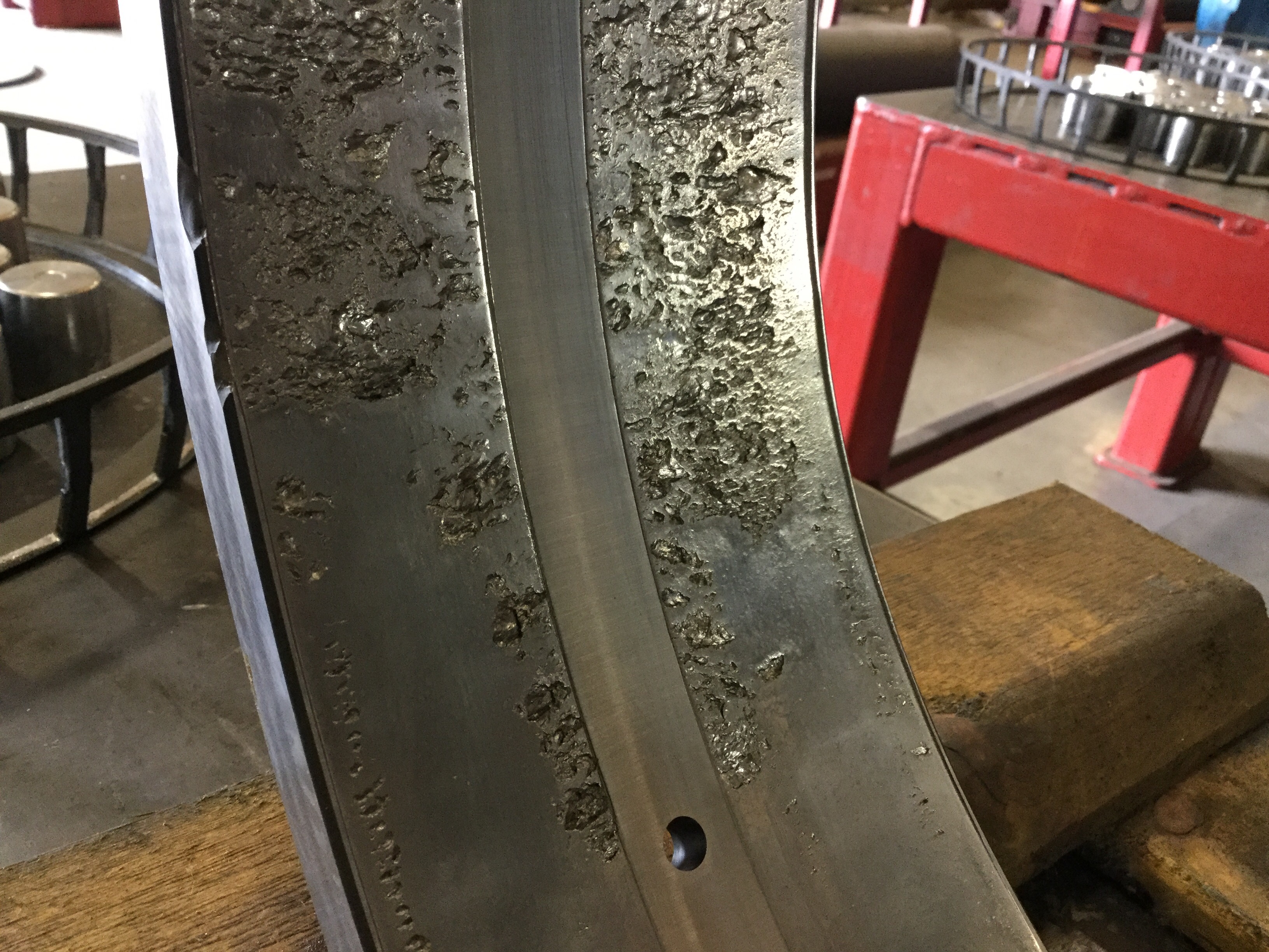
What was seen in the least damaged bearing is typical of these applications, a load zone that spans about 120 degrees. This is the area of the outer race that is carrying the load of the application. At each end of the load zone, the load in itself lessens to zero and the pattern has a tapered look.
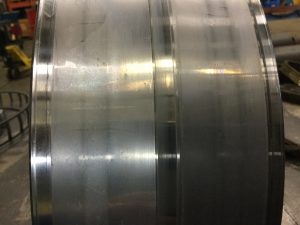
Photo Credit: Douglas Martin.
What is typical of conveyor bearings is the area in which the roller is entering into the load zone. Often, a rectangular worn area, which is the full width of the roller path at the start of the load zone, is seen. It is believed that at this “entry” into the load zone, the roller is not turning with the same surface speed as the race and as it gets loaded it begins to rotate. During this period of “no rotation” the roller is sliding across the race. Due to abrasive particles in the grease, this sliding abrasively wears the race. It is as if each roller is a piece of sandpaper wiping
across the raceway.
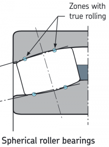
Photo Credit: Douglas Martin.
Once the roller is fully loaded, it achieves the needed rolling velocity and there is rolling contact. With rolling contact the wear rate is significantly reduced. As with all rolling elements, there are two zones of rolling contact that surround a zone of sliding contact.
If this bearing was rotating fast enough and had a good lube film, there would be no metal-to-metal contact. However, since conveyor bearings are going relatively slowly, there will be some degree of metal-to-metal contact. The degree of wear will then be a function of how effective the lubricant’s additive package is.
As this bearing turns the centre section of the roller, contact slides and wear occurs. Then there are two bands of rolling contact, and beyond them to the roller end is sliding contact. Since the load on a roller is heaviest at the centre and lightest at the ends, there is a corresponding drop in the rate of wear as one moves from the centre to the ends of the roller.
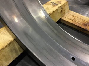
Photo Credit: Douglas Martin.
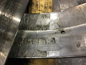
The centre area of the rollers and race wear faster than the outer edges. Eventually what happens is that the roller develops a flat spot between the rolling contacts. This will essentially shift the heaviest contact of the roller from its centre to the less worn areas just past the pure rolling areas. Since the load is now carried over a smaller area, fatigue cracking will set in.
This is seen not in the centre of the races, but on either side of the centre. We see a smoother flat area between the fatigued areas of this outer race. Once the raceway begins to fatigue and flake, the generated steel particles act as abrasive particles, further accelerating the wear process. At some point in time, the ring itself may begin to fracture as it is worn thinner.
So What’s the Solution?
One answer may be to improve the sealing to prevent the ingress of abrasive particles. Another solution may be to increase the frequency of re-lubrication to purge out the contamination.
However, the issue may also be that the speed of rotating may be too slow to create a lubrication film. The only way to address this is to use a lubricant with a proven additive package or even solid additives.