Gas turbine operational troubleshooting
Gas turbine efficiency can be determined by concentrating on troubleshooting four important areas: gas path analysis, fuel control systems, vibration, and lubrication.
October 31, 2022 | By L. (Tex) Leugner
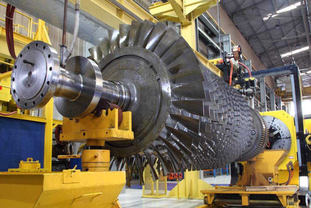 Photo: Photosoup/Getty
 Photo: Photosoup/Getty
The gas path consists of the compressor, combustor, and turbine, all of which are susceptible to damage by contamination, fouling, erosion, corrosion, sulphidation, nitration, oxidation, water emulsions, plugged or damaged fuel or turbine nozzles, and broken blades or vanes.
Q | Does the maintenance group fully understand the gas path parameters necessary to correct combustion problems?
LOGIC: Compressor fouling occurs due to foreign deposits on the blades, plugged or damaged fuel nozzles and damaged combustor liners. Normal operation depends on fuel flow, exhaust gas temperature and compressor discharge pressure. The turbines cycle signature is related to power output, corrected turbine inlet temperature, rotor speed and performance factors including pressure, temperature, speed, fuel flow and BHP.
Q | Does the maintenance group understand how to monitor and manage fuel and governor controls?
LOGIC: Problems such as ‘hot’ starts are usually caused by a too rich fuel schedule, while ‘hung’ starts may be the result of a too lean fuel schedule. Running problems such as an inability to accelerate, or a too rapid acceleration, are usually caused by a governor problem. Both pneumatic and hydraulic governor controls are susceptible to leaks, contamination, and wear. Pneumatic systems can also be erratic if moisture is in the air lines. The trouble-shooter must know how the control systems work, how to recognize malfunctions and verify corrosion, erosion, and foreign damage with a borescope inspection.
Q | Does the turbine maintenance group have a well-designed vibration monitoring schedule?
LOGIC: Vibration analysis is an essential element of condition monitoring of gas turbines. Gas turbine bearing problems are related to lubricant quality, contaminants, wear, temperature and vibration. Rotational speeds of aero-derivative turbines may run at speeds ranging from 9,000 to 20,000 RPM, while heavy industrials operate at speeds in the 3,000 to 12,000 RPM range. All new aero-derivatives and most industrials now use rolling element bearings to support rotors and shafts more effectively.
The vibration frequencies related to anti-friction bearings are fundamental train frequency, ball pass frequencies of the inner and outer raceways, and the ball spin frequency. These frequencies depend upon rotor speed and bearing geometry. Trouble-shooters should know the name and part numbers of gas turbine rolling element bearings to obtain the manufacturers bearing geometry data and thus know the frequencies of the bearings. The bearing geometry data required to accurately calculate vibration fault frequencies are ball or roller diameter, pitch diameter, number of rolling elements and contact angle. If the bearing frequencies are not known, or cannot be obtained from manufacturers, the following calculations can be used to obtain the approximate frequencies of the bearings inner and outer raceways.
Inner Race Frequency
# of Rolling Elements X Shaft RPM X 65 per cent
Outer Race Frequency
# of Rolling Elements X Shaft RPM X 45 per cent
Resonant frequencies are found in every piece of equipment and turbines are no exception. Resonant frequencies that may affect turbine operation can be found in rotors, base plates, mounting pads, piping, and bearing or bearing supports. Other sources of vibration include rotor imbalance, looseness, and misalignment. To obtain as much vibration data as possible, it is wise to measure displacement, velocity, and acceleration. Proximity transducers are recommended to measure displacement at radial bearings. Accelerometers are used to measure high frequencies of turbine blade vibration, while the most uniform measurement of vibration data is velocity to detect a wide range of vibration data occurring at low, mid, and high frequencies. Vibration data should be collected in the vertical, horizontal, and axial positions.
Q | Is the maintenance group fully aware that proper turbine lubrication is critical?
LOGIC: High operating temperatures and catalysts like water and air cause oxidation and thermal degradation of the oil that generate varnish and sludge. Oxidation is a chemical reaction when oil is mixed with oxygen. Thermal degradation occurs in the combustor at temperatures around 205ºC (400ºF) or higher, or when trapped air bubbles travel from low to high-pressure areas. The hot air bubbles implode, and the high concentration of heat raises the oil temperature dramatically.
Symptoms of nitrogen oxides and oxidation include an increase in viscosity, acid number and oil discolouration, all of which indicate serious degradation that results in tar-like deposits on mechanical seals, varnishing on inlet vane valves or bearings, thick deposits trapped in oil filters and premature plugging of oil coolers.
Electrostatic discharge occurs in lubricants due to internal molecular friction and differences in electrical potential between the fluid and component surfaces and contributes to varnish and sludge formation. Static electrical discharge occurs at servo valve surfaces, in filters and reservoirs and spark discharges can reach temperatures of 20,000ºC, promoting thermal degradation instantly.
Static discharge can be heard if one is close enough to the reservoir of an operating turbine where this is occurring. As little as 500 PPM of water can promote foaming, emulsions, and bacterial growth. Oil sight glasses may show these conditions. Contaminants will cause scoring and wear on bearings and control valves in governor systems. Other contaminants include water/glycol mixtures in coolers, and it is recommended that the oil side operating pressure of the cooler be higher than the water side operating pressure.
Q | Does the maintenance group use the best techniques available for turbine lubricant analyses?
LOGIC: A typical 250-hour turbine oil analysis report should reflect the following results.
Membrane Patch Colorimetry: measures varnish potential; a varnish potential of 35 or less is normal, 50 and higher is considered severe.
Remaining Useful Life Evaluation Routine (RULER): measures the antioxidant additives (amines and phenols), in turbine oil by ASTM D6810-02 or D6971. RULER result of 50 per cent provides a warning, any result of 20-25 per cent indicates immediate action required.
Ultracentrifuge (UC): determines the level of insoluble contaminants that indicate varnishing, zero reflects new oil, four is considered marginal and a UC value exceeding six is critical.
Total Acid Number (AN): is an indication of the remaining useful life of a lubricant by ASTM D664 or D974. New turbine oil has an AN of about 0.03 and in service turbine oil must not exceed 0.2.
Water by Karl Fischer: by ASTM D6304, determines the amount of water. Acceptable water levels are less than 500 ppm, unacceptable levels are 1000 ppm.
ISO Particle Count 4406: measures the number of particles in lubricants in size ranges of four, six and 14 microns by optical particle counter. New turbine oil cleanliness standards are 16/14/12 or as specified by the turbine manufacturer. In service turbine lubricant cleanliness levels should never exceed 18/15/13. When any combination of these results indicate unacceptable contamination levels, increased varnish potential, or a build-up of insoluble materials, immediate action is recommended.
_____________
L. (Tex) Leugner, the author of Practical Handbook of Machinery Lubrication, is a 15-year veteran of the Royal Canadian Electrical Mechanical Engineers, where he served as a technical specialist. He was the founder and operations manager of Maintenance Technology International Inc. for 30 years. Tex holds an STLE lubricant specialist certification and is a millwright and heavy-duty mechanic. He can be reached at texleug@shaw.ca.